KWS Electronic Test Equipment GmbH

VAROS Connect
Zum Produkt

VAROS Connect
Zum ProduktVAROS Connect
Zum ProduktHier finden Sie uns:

Adresse
KWS Electronic Test Equipment GmbH
Raiffeisenstr. 9
83109 Großkarolinenfeld/Tattenhausen
Germany
Telefon+49 8067 90370
Fax+49 8067 903799
Entdecken Sie mehr von uns
Über uns
KWS is located in Tattenhausen, Upper Bavaria. We have been developing, producing and distributing antenna measuring instruments of the highest quality for more than 60 years. Our devices are characterized by highest measurement accuracy, long durability as well as simple and intuitive operation. Depending on the requirements, different product families are available for your measurement tasks - no matter whether in local SAT distributions or complex cable networks.
In addition to the products, KWS offers a wide range of services. Whether training, repairs or loan equipment. We help you quickly, uncomplicatedly and cost-effectively.
We have made it our business to offer you one-stop solutions in the field of signal transmission. For this purpose we have further selected products in our program to support you in tasks and projects in the field of signal transmission. Over the last few years, we have successively expanded our portfolio to include all areas of signal transmission.
This includes for example:
- Splicing technology and OTDRs from Inno Instrument
- Tools from Miller and Jonard
- Sticklers cleaning tools from MicroCare
- passive components in copper and optical fiber from the manufacturers TKM, Corning, Omelcom...
- For all our products we offer the same service as for our measuring receivers. Starting with consulting and training up to repairs, calibrations and rental equipment.
We are looking forward to you!
Unsere Produktgruppen
Downloads
Keywords
- Einblastechnik
- Spleißtechnik
- OTDRS
- Glasfaser
- FTTx
Unsere Produkte
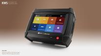
VAROS Connect
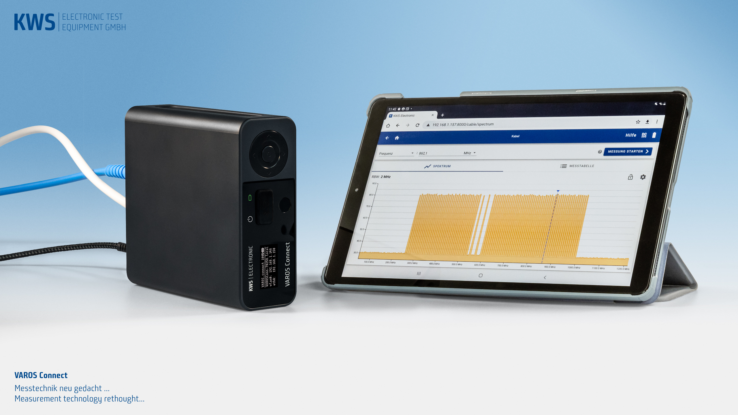
VAROS Connect: Measurement technology rethought…
The devices of the VAROS Connect series are the next logical step into the future. Here we rely on proven quality without compromising on measurement technology. And we integrate them into a modern, contemporary application.
The main difference to existing models is the separation of the measurement technology and the operation handling. This opens up a wide range of possibilities in hardware design and offers almost unlimited options for networking with other hardware or for integration into modern measurement systems.
Operations can be displayed on any WLAN-capable terminal device—be it a laptop, tablet or smartphone. Our new user interface can be optimally displayed in any modern browser, regardless of the platform.
Displaying on any end device provides great design flexibility for the graphical user interface. We have taken advantage of this to make navigation more intuitive. Despite the many innovations, the transition between a VAROS or AMA series device remains easy thanks to the integrated help.
4 devices—4 solutions
VAROS Connect will be successively extended into an entire family of measuring instruments. The introduction of the VAROS Connect models 201, 202, 203 and 204 is underway, and the range of functions of the respective devices is being expanded as the model number increases.
VAROS Connect 201 and 202 have all the features that a modern combination measuring receiver needs. With extensive functions for all common measuring ranges, both devices leave nothing to be desired. They are distinguished by the optical receiver, which is integrated in the VAROS Connect 202 type.
In parallel, both measuring receivers can be upgraded with a modern DOCSIS 3.1 modem—resulting in the VAROS Connect 203 and 204 types (without or with optical receiver).
- Frequency range from 5—2,350 MHz
- MPEG-H (HEVC)/UHD decoder with image display
- DOCSIS 3.1 modem with comprehensive analyzer
- Complete SAT functions with DiSEqC, UNICABLE and JESS according to the latest standard
- Constellation diagram for all ranges
- WLAN-capable devices with API for integration into planning and documentation systems (e.g. AND)
- Interfaces: USB 3.0, USB-C 3.0, RJ45, WLAN, HF
- Display and control elements on the device for basic settings
- Extensive documentation functions
GUI
The new user interface of the VAROS Connect series reorganizes proven knowledge. We use the possibilities of a modern software architecture and design our GUI in the most intuitive way possible.
In order to ensure optimal operation on all end devices, the user interface is designed to be responsive and automatically adapts to the display capabilities of each end device. Since the already installed web browser is used, no proprietary applications are necessary.
We have integrated intelligent help into our user interface that assists you in using and interpreting the measured values—always based on the current view.
Connectivity
In spite or precisely because of the decoupling of the display and measuring unit, many interface connections are important. Here we rely on a variety of modern interfaces for maximum connectivity. Every device in the VAROS Connect family has a USB-A, USB-C and RJ45 input and, of course, RF input. The VAROS Connect 202 and 204 also have an optical input.
Measurement ranges
SAT, antenna or cable: all VAROS Connect devices are comfortable in the DVB-C / T / T2 / S / S2 / S2X, DAB and DAB+ measurement ranges. A responsive constellation diagram is available in all measurement ranges.
The SAT range also has DiSEqC 1.x and 2.0 functions. In addition, the measuring device processes JESS and Unicable programming according to the latest standard.
DOCSIS 3.1
The VAROS Connect 203 and 204 devices also have a DOCSIS 3.1 modem with extended functions and an analysis function. This additional feature makes the device particularly interesting for cable network operators and complex service providers.
However, at a time when IP services via coaxial distributions are increasingly important, it also brings added value for every electrical installation company. At the same time, it opens up the possibility of handling tasks of cable network operators.
Image display
The image display of the VAROS Connect series is state-of-the-art. All devices are able to analyze and decode video signals. This includes H.264 and H.265 (4K). The integrated HEVC decoder allows detailed analysis of the transport stream and display of the analyzed content image.
This feature is particularly advantageous for interference suppression at the end customer’s premises: it can be used to prove the quality of the signal at the transfer point and to identify possible defects in the end devices.
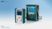
VIEW 600—Modular OTDR
VIEW 600—Modular OTDR with high performance
The INNO Instrument View 600 can handle all measurement tasks in optical networks. Thanks to its modular design, it can be equipped with 13 different modules and therefore leaves nothing to be desired. In addition to the extremely precise measurement results, the very powerful CPU allows a very short reaction time.
In combination with the high-quality capacitive touch screen and the intuitive user interface, already known from other devices, the View 600 convinces in every respect.
- 13 modules applicable
- SOLA (Smart Optical Link Analyzer)
- 7″ Touch screen with smart GUI
- 8 GB storage with internal SD Card & external USB memory
- Built-In VFL, light source and OPM
OTDR (Optical Time Domain Reflectometer)
OTDR mode allows you to measure distance, loss, reflectance, attenuation, ORL and sum on an optical fiber. In Auto mode, the test is automatically performed without further adjustments. Test results can be stored in 3 types of formats (image, SOR, PDF).
SOLA (Smart Optical Link Analyzer)
SOLA (Smart Optical Link Analyzer), an application that simplifies the measurement process, shows you accurate test results using an advanced algorithm and an optimal multiple pulse width. You do not need to set complicated parameters, which means that even unskilled workers can perform measurements with great ease.
VFL (Visual Fault Locator)
VFL (Visual Fault Locator) visually identifies the location of the bending point, defective connector or splice point by emitting a bright red laser (it can reach a maximum of 10 km), and this is an essential function for field technicians.
Fiber microscope
Testing the end-face of the fiber on connectors with a fiber optic microscope is very important, as a contaminated or damaged connector can cause critical damage to the test results as well as to the test port.
OPM (Optical Power Meter)
OPM (Optical Power Meter) is used to accurately measure optical power on fiber optic networks operating at 850 nm, 1,300 nm, 1,310 nm, 1,490 nm, 1,550 nm, 1,610 nm and 1,625 nm.
Light source
Invisible light source (1,310 / 1,550 nm) can provide the following sources of light: CW, 1 kHz, 2 kHz modulated and 1 kHz & 2 kHz blink.
Specifications
- Model: View 600
- Display: 7 inches, high brightness TFT LCD, resolution of 800 × 480 px
- Distance units: m / km / mile / ft
- Range settings (km): 1.3, 2.5, 5, 10, 20, 40, 80, 120, 160, 360 km
- Range settings (mile): 0.81, 1.55, 3.11, 6.22, 12.4, 24.8, 49.6, 74.6, 99.4, 232.7 mile
- Pulse width: 5 ns, 10 ns, 20 ns, 50 ns, 100 ns, 200 ns, 500 ns, 1 μs, 2 μs, 10 μs, 20 μs
- Distance accuracy: ± (1 m + distance × 2.5 × 10⁻⁵ + sampling resolution)
- Linearity: 0.03 dB
- Sampling points: 256,000 points
- Refractive index: 1.000000—2.000000 (step: 0.000001)
- Splitting ratio: Up to 1:128 splitter
- Resolution: 0.04 m ~ 10.24 m
- Loss readout resolution: 0.001 dB
- Battery capacity: Operating time: Up to 12 hours
- File format: SOR, BMP, JPG, GDM, SOLA, PDF
- External connection: 2× USB 2.0
- Compatible connector: APC (FC, SC, LC), UPC (FC, SC, LC, ST)
- Power supply: AC Input 100—240 V, 50—60 Hz / DC Input 19 V, 3.42 A
- VFL port: 2.5 mm ferrule type
- VFL wavelength: 650 nm ± 10 nm
- VFL distance: Up to 10 km
- VFL output power: 20 mW
- Light source: Operating wavelength 1,310 nm / 1,550nm ± 10 nm
- Light source output power: −5 dBm
- Wave lenght: 1,310 nm / 1,550 nm
- Wavelength calibration (OPM): 850 / 1,300 / 1,310 / 1,490 / 1,550 / 1,625 / 1,650
- Power range (OPM): −70 to +6 dBm (Accuracy: 0.01 dB)
Software features
- Softwareupdate: Simple update with USB memory stick
- Auto mode: Automatic optimization of parameters and test process
- INNO PC Program: A tool for analyzing and revising the test results of OTDR and SOLA
- PDF reporting: Providing the test report in PDF format
- PDF viewer: PDF file can be viewed on the screen
- Transmission via USB / Wi-fi: Quick transmission of test results via USB and Wi-Fi
- Link with printer: Printing by connected printer
- Distance editing: Manually changing distance on OTDR mode
- Identifying macro-bending: Identifying micro-bending on OTDR or SOLA mode
- Operation with mouse: Easy operation with mouse (linked to USB port)
Delivery contents
- OTDR View 600
- Power cable / AC adapter: ACC-25 / JS-180300
- Carrying case with shoulder strap: Soft case
- Touch pen
- Calibration certificate
APC connector
To improve test efficiency and optimize the OTDR function, it is recommended to use the APC connector and plug it to the MINI 2 SM port, due to the low reflectance it causes. The reflection coefficient is the key parameter that will affect OTDR performance and particularly the dead zone (APC connector performance is better than UPC connector performance).
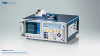
AMA 310—TV analyzer
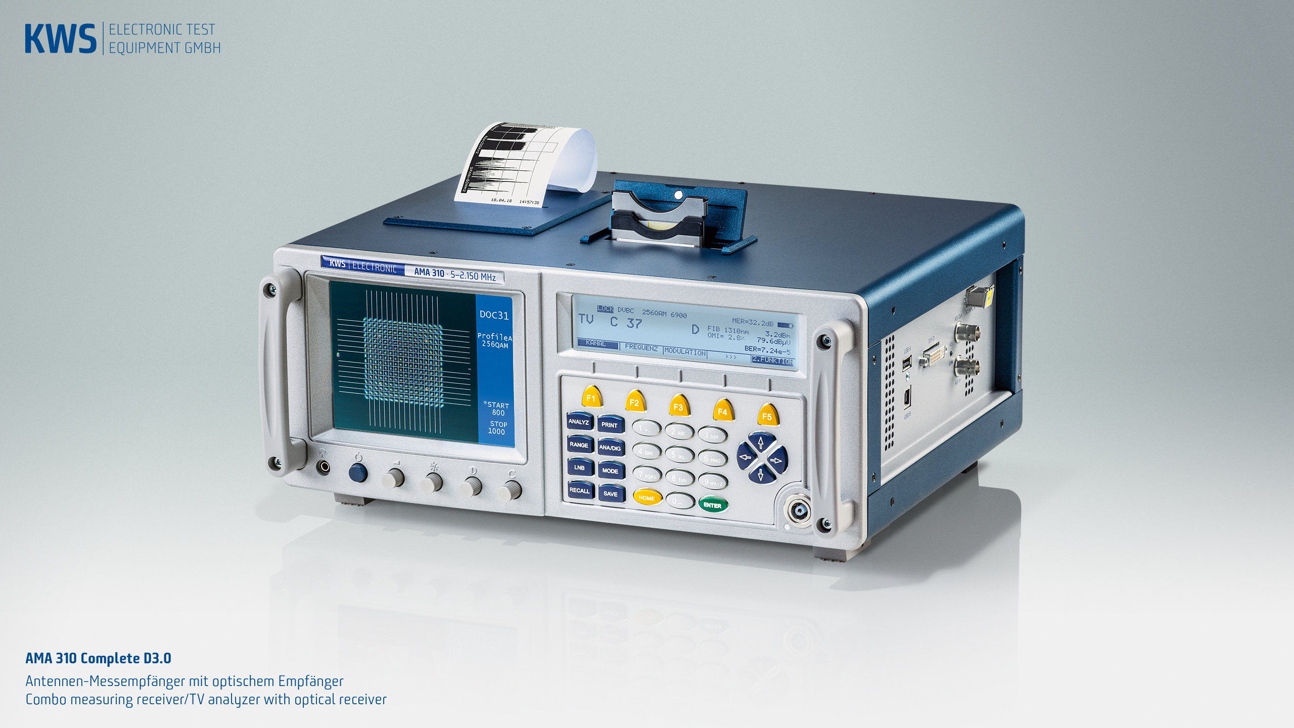
Measurement technology for professionals: TV analyzer AMA 310 Complete D3.0.
The new AMA 310 Complete D3.0: classic measurement technology in unrivaled Rich equipment and efficiency. No test receiver is easier to use, no one makes working easier, even with very complex error analyzes. It is fully equipped for all RF measurements and DOCSIS 3.1 measurement modules can be ordered as options.
In addition to the identical RF measurement branches, optical signals can also be measured and processed, regardless of whether the device is connected to a SAT system or a CATV network.
Whether with large-scale satellite systems or CATV networks, the optical signal transport is becoming increasingly important: The immense advantage of this technology is that long distances energy-saving and potential-free managed. The transmission is different, but the procedures remain the same; Do not miss out on familiar procedures—that is the key factor for the AMA 310 Complete D3.0. Everyone who works with this device benefits from a perfect combination of conventional and well-known RF measurements and the added accuracy of error analysis by injecting optical signals.
Great problems often cause the optical connections. Even a slight contamination of plugs or fibers can lead to incorrect measurements. The optical device connection of the AMA 310 is optimally protected against contamination by a mechanical shutter.
The standard equipment is a UHD decoder for displaying ultra-high-resolution image content and, of course, an extended CATV frequency range up to 1,214 MHz.
Also, the requirement for the documentation of equipment whether tabular measurement series in .xml format, whether screenshots of errors or records of long-term measurements can be easily met with him.
The many years of experience and the consistent further development of the AMA 310 concept from KWS Electronic have created a measuring device that is just as unbeatable in terms of features and precision on the market: whether DOCSIS 3.0 or 3.1, DVB-C or Ultra-HD ,
The AMA 310 Complete D3.0 is the standard that others need to measure.
- High resolution bright 5.5″ colour TFT
- Frequency range of 5-2,150 MHz – for TV/FM/return channel 5–1,214 MHz, for SAT 910–2,150 MHz
- Digital: DVB-S, DVB-S2, DVB-C, DOCSIS 3.0, DVB-T, DVB-T2, DAB+
- Analog: VHF, TV
- Return channel: level, BER, MER and constellation diagram in conjunction with VAROS 107
- DOCSIS-Analyzer (DOCSIS 3.0)
- Optical performance: OMI (optical modulation index), BER/MER/PE (packet error), constellation diagram, spectrum analyzer, data grabber
- EMI measurement
- MPEG-H (HEVC)/UHD decoder with 2 CI slots (SD/HD/UHD/DVB T2 image display)
- Real-time constellation diagram (except DVB-T2)
- Hum and phase jitter detection
- CATV: MER up to 40 dB
- Digital analyzer for all areas with TILT measurement, ingress measurement
- Echo measurement for DVB-T (impulse response)
- Teletext analog/digital, DVB subtitling
- DiSEqC, UNICABLE, JESS (EN 50494 und 50607)
- Programming function for addressable antenna doses
- Signal quality monitoring with Datagrabber
- USB, SCART in/out, DVI out, Ethernet (RJ 45)
- Lithium ion battery pack 14.4 V/6.6 Ah
Optical receiver (SC/APC)
The AMA 310 Beta is equipped as standard with an optical receiver. The following measurements/functions are possible:
- Optical performance
- OMI (optical modulation index)
- BER / MER / PE (package error)
- Constellation diagram / Spectrum Analyzer / Databrabber
- Optical signals can also be documented.
The quality for the professional
Because of its optimum features and its easy handling, this measuring receiver is appreciated by all users … and in detail the difference lies: Fast calculation and operating processes, high-resolution image and graphic representations characterize the AMA 310 Complete D3.0. Useful copy and save functions help you to troubleshoot and document assets.
MPEG-H (HEVC)/UHD decoder.
UHD TV is increasingly gaining ground. As with the transition from SD-TV to HD-TV, more powerful compression techniques are used. With the new MPEG-H (HEVC)/UHD decoder ultra-high-resolution image content can be displayed.
With this decoder, the image display of all DVB-T2 content is possible. The HEVC standard used in Germany is a further development of the previous standard (MPEG-4). The transmission of Full HD programs via DVB-T2 (Germany) is one of the first distribution channels in which HEVC is used throughout the country in regular operation.
DOCSIS Analyzer 3.0
With the DOCSIS Analyzer 3.0 EURO and US-DOCSIS signals can be evaluated. Channel bonding is graphically displayed. The measurement of the downstream quality as well as the upstream transmission level is possible.
DVB-T2 measurement module
DVB-T2 differs severely from the DVB-T standard. With the new DVB-T2 it is possible to transmit HDTV services. The echo measurement is an important evaluation of the signal reserve.
DAB / DAB + measuring module
Digital radio in the two standards DAB and DAB + is steadily gaining in importance. The metrological evaluation, the reading out and demodulation of the services is standard on the AMA 310.
Measuring with results.
The modern housing concept and future-oriented battery management make the measuring receiver even more ergonomic. Despite high component integration, all prescribed EMC guidelines are complied with. For this reason, it is virtually impossible for KWS measuring devices to interfere with each other and thus display falsified measuring results.
CATV frequency range up to 1,214 MHz
More and more cable network operators are converting their systems to 1 GHz bandwidth. The picture shows a spectrum in the frequency range 45 to 1,214 MHz.
Electromagnetic interference (EMI) measurement
Since May 2009, the Federal Network Agency (BNetzA) has been testing cable networks for compliance with the maximum permissible limits of interference field strengths. This check is based on legal requirements (SchuTSEV) in order to protect safety-relevant radio frequencies against interference.
Printer
The integrated printer enables documentation on site in paper form. The option is ideally suited to create a proof of the measurements taken as well as the digital documentation as well as immediately.

VIEW 8X—Core alignment splicer
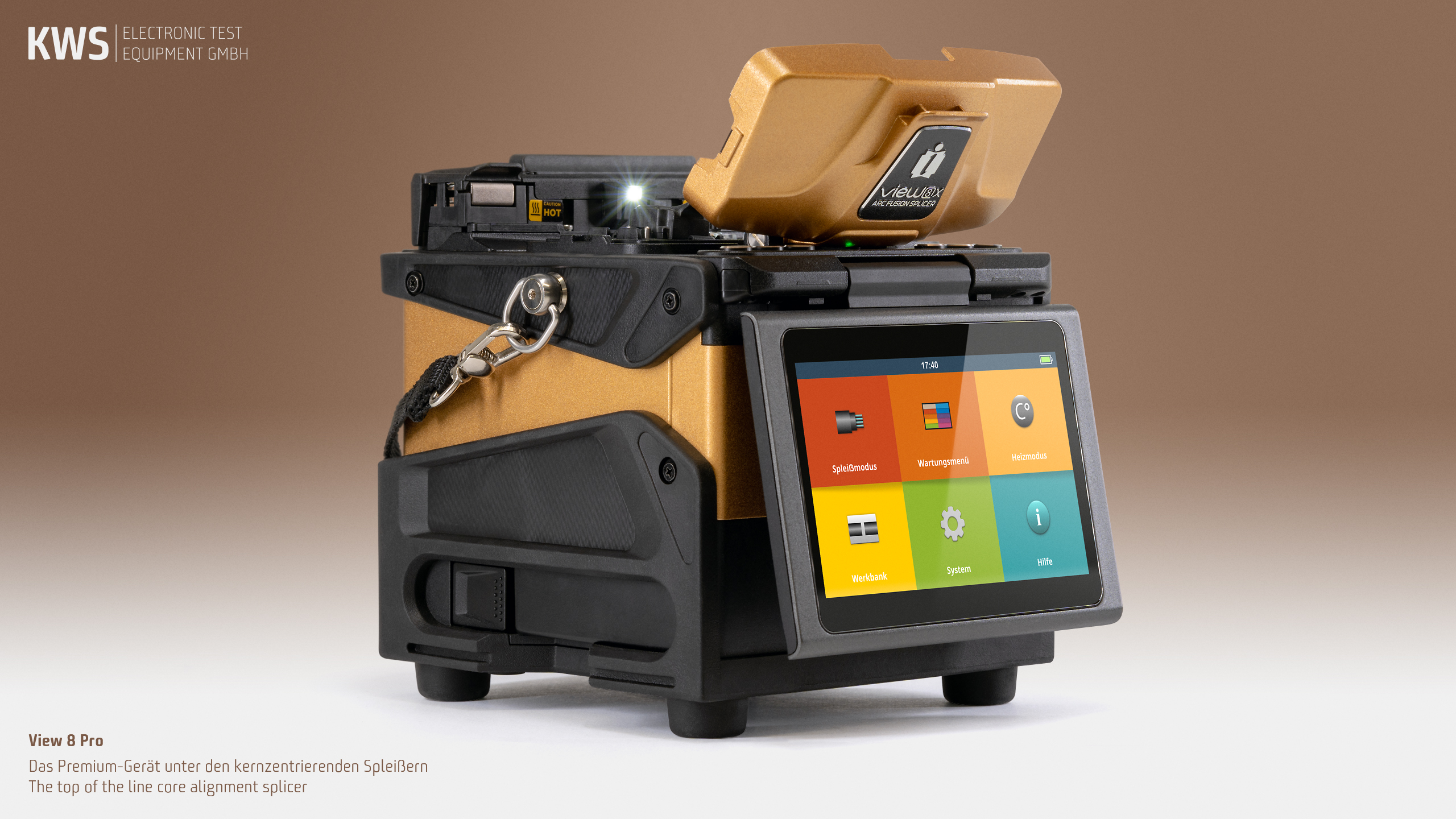
VIEW 8X—The top of the line core alignment splicer
The View 8X from INNO Instrument is a first-class core alignment splicer. The X stands for “eXceed eXpectations”—and that’s exactly what the View 8X does: it exceeds your expectations. The South Korean high-end manufacturer’s flagship sets the benchmark for splicing efficiency. Period.
This device’s features are not lacking in superlatives: Splicing time: 4 seconds. Heating time: 9 seconds. Battery power: 500 work cycles. Magnification: 520 ×. Plus a high-resolution 5-inch color LCD touchscreen, intuitive user interface, robust design, large memory for measured values and documentation images. The View 8X is not to be overlooked.
A decisive added value of INNO splicers is the integration into the free View Pro Cloud Management System, which enables an entirely new level of remote management. The web-based application enables onsite staff and back-office management to optimize workflows, generate comprehensive evaluations and much more.
- Core alignment
- High-speed splicing and heating
- Large battery capacity
- Bright operating light
- Versatile fiber holder
- 5-inch color LCD touch screen
- Intuitive operation with smart GUI
Specifications
- Model: View 8X
- Number of fibers: Single
- Alignment method: Core alignment
- Applicable fibers: SM (ITU-T G.652 & G.657) / MM (ITU-T G.651) / DS (ITU-T G.653) / NZDS (ITU-T G.655)
- Coating diameter: 100 μm to 3 mm
- Cleave length: 5 to 16 mm
- Cladding diameter: 80 to 150 μm
- Splice programs: Maximal 128 modes
- Heating programs: Maximal 32 modes
- Typical splice loss: SM: 0.01 dB / MM: 0.01 dB / DS: 0.03 dB / NZDS: 0.03 dB / G.657: 0.01 dB
- Splice time (typical) *: Quick mode: 4 seconds / SM mode 5 seconds / Auto mode: 7 seconds
- Heating time: Quick mode: 9 seconds / Average: 13 seconds
- Protection sleeve: length 20 to 60 mm
- Display: 5.0” Color LCD display, Full Touch Screen
- Fiber view: X, Y, XY, X/Y
- Fiber display (magnification): × 360 and × 520
- Return loss: > 60 db
- Data storage: Last 20,000 (values) or 10,000 (images) results
- Pull test: 1.96 to 2.25 N
- Operation: Keys / Touchscreen
- Lighting: White LED
- Power supply: AC input 100 to 240 V / DC input 9 to 19 V
- Battery *: Capacity: 9,000 mAh / Typical operation cycles: 500 cycles (splicing and heating)
- Electrode life span: 6,000 arc discharges
- Data output: Cloud (View Pro Manager) and USB-C
- Operating conditions *: Altitude: 0 to 5,000 m above sea level / 0 to 95 % relative humidity (non-dew) / −10 to 50 °C / Max wind 15 m/sec
- Storage conditions *: 0 to 95 % relative humidity (non-dew) / −40 to 80 °C
- Tests: Water resistance (IPx2) Rain resistance: 10 mm/h for 10 minutes / Shock resistance 76 cm for bottom surface drop / Dust resistance (IP5X) Exposure to dust: 0.1 to 500 μm diameter aluminium silicate
- Dimensions in mm (Height × Width × Depth): 162 × 143 × 158
- Weight: 2.68 kg
* Splicing time: measured from the time of fibers entering the screen until the estimated loss is displayed. Splicing time can vary depending on calibration status.
* Battery: Measured as a one-minute splicing and heating cycle. Measured in energy-saving mode.
* Opreating/Storage conditions: Responsibility for damage resulting from misuse of the product is not accepted.
View Pro Manager
Another key added value of the View 8X is its integration with the free View Pro Cloud Management System, which offers a whole new level of remote management.
The highlights
- The real-time tracking function shows where the splicer is at any given time—forgetfulness and theft are finally a thing of the past. And pop-up messages provide quick information on the status of the device.
- With device management, you can keep an eye on a warning about an electrode or a calibration to be performed, for example, at any times. And software updates can even be imported directly from the cloud.
- All reports and data are exchanged online and are therefore immediately available, even if the device remains on a remote construction site. A physical readout via USB is still possible as an option.
- Work/task management automatically archives the work progress of each device. Workforce planning has never been easier and efficiency gains are immediate.
All functions are controlled or accessed from the dashboard on the PC or mobile phone connected to the INNO iCloud server. The View 8X in turn communicates with the server via a 4G / 5G cellular network. All it needs is a low-cost IoT SIM card and the splicer is on the web. And all the information is available as quickly as possible and always up to date.
Scope of delivery
- Splicer View 8X
- Cleaver V12
- SOC Holder FH-SOC-R
- SOC Heater cover HTS-SOC-02
- AC Adapter JS-180300
- Cooling tray CG-23
- Electrodes E-70
- Battery pack LBT-30
- Power cable ACC-25
- USB cable USB-7P
- Carrying case ICC-55
- Shoulder strap ST-01
Accessories
In addition to the splicer, various tools are required for the correct preparation of the fibers. If you are not yet equipped for this, we are of course happy to help. Whether it’s a suitable stripper, a loose tube cutter for loose tube, cleaning fluid and cloths or a crimping press, we can provide everything. And we’re here to help and advise you. Talk to us or get an initial overview online.
VAROS 106—Combo measuring receiver/TV analyzer
Smaler, lighter, more powerfull…VAROS 106—Combo measuring receiver/TV analyzer.
Welcome to the new, digital world—the VAROS 106, with groundbreaking design, easy operation and all available measurement options.
No other device on its clear display makes such a simple and understandable signal evaluation possible or has implemented so many new and innovative measurement methods. With the integration of some tools, the VAROS 106 supports the local craftsman…It has never been so easy to create a documentation of the measured values for the client and to pass over faultlessly functioning systems.
The VAROS 106 includes as standard equipment a UHD decoder for displaying ultra-high-resolution picture content and the new DAB+ radio. Of course, all SAT CATV and terrestrial signals can also be measured. A measuring receiver for the future-oriented craft.
A common requirement is the documentation of distribution systems. Whether tabular measurement series, screenshots of defect images or long-term measurements: the VAROS 106 can do it…
- High-resolution, bright 5.7″ color TFT
- Frequency range of 5–2,150 MHz – for TV/FM/reverse channel 5–1,214 MHz – for SAT 910–2,150 MHz
- DVB-S, DVB-S2, DVB-C, DVB-T, DVB-T2, DAB+
- Digital: level measurement, BER, MER, noise margin, packet error, NIT evaluation
- Keyboard with switchable backlight
- Analog: Level measurement for return channel, FM and TV
- EMI measurement (interference field strength)
- Spectrum Analyzer for all areas/TILT function
- Constellation diagram for all areas
- Echo measurement for DVB-T/-T2 (impulse response)
- SCAN function for secure satellite detection
- DiSEqC, UNICABLE, JESS (EN 50494 and 50607)
- Direct programming function for JESS antenna outlets
- Signal quality monitoring with Datagrabber
- Measurement data storage/screenshots/channel plans directly via USB
- Video/audio output via DVI
- Lithium ion battery pack 7.2 V/10.1 Ah
VAROS 106: Modular and innovative
The KWS-typical modular device concept was also adopted by the VAROS 106 and leaves room for innovation.
The VAROS 106 is also an investment in the future. Applications that may not play a role today can still be retrofitted in years.
MPEG-H (HEVC)/UHD decoder
UHD TV is increasingly gaining ground. As with the transition from SD-TV to HD-TV, more powerful compression methods are used. With the new MPEG-H (HEVC)/UHD decoder ultra-high-resolution image content can be displayed.
With this decoder, the VAROS 106 is also capable of displaying all DVB-T2 content. The HEVC standard used in Germany is a further development of the previous standard (MPEG-4). The transmission of Full HD programs via DVB-T2 (Germany) is one of the first distribution channels in which HEVC is used throughout the country in regular operation.
DAB/DAB+
Digital radio DAB and DAB+ will gradually replace FM. The metrological evaluation, the reading out and the demodulation of the services are standard features of the VAROS 106.
Forward-looking standard: DVB-T2
The new DVB-T2 differs severely from the DVB-T standard. With DVB-T2 it is now possible to transmit HDTV services. The echo measurement is an important evaluation of the signal reserve.
S/N measurement module
The evaluated S/N measurement is used to measure the signal-to-noise ratio of an analog CATV channel in accordance with standards. It is possible to safely assess the signal quality of analog TV signals.
Electromagnetic interference measurement (EMI)
Since May 2009, the Federal Network Agency (BNetzA) has been testing cable networks for compliance with the maximum permissible limits of interference field strengths. This check is based on legal requirements (SchuTSEV) in order to protect safety-relevant radio frequencies against interference.